
Biofouling as a natural process
Biofouling is a natural process occurring at all three phase transitions: water to hard substrate, such as barnacles and mussels; air to substrate, such as lichens; and air to water with its specialised micro-plankton in the surface microlayer.
Cooling water systems
Electric power plants use huge amounts of water to complete the steam cycle. Steam from the low pressure side of the turbines is condensated in large mainly tubed heat exchangers or condensers. The condensated water is re-used after cleaning in the steam cycle. This process of condensation uses large quantities of cooling water. In general a fossil fuelled power station uses circa 25 m³/s at a thermal discharge of 600 MWth.
Such volumes make it uneconomical to use treated or tap water, so the sources are rivers, lakes and coastal water. These surface waters contain a large range of biological species, including larvae of crustaceans and bacteria. Bacteria can cause slime build-up in heat exchangers, reducing heat exchange capacity and contributing to microbial influenced corrosion. The planktonic larvae of barnacles, mussels and oysters can attach in all parts of the cooling system and form thick mats in conduits and other plant structures.
Uncontrolled colonisation by micro- or macrofouling organisms can reduce efficiency and may finally shut down a plant. In the current global economy there is increasing pressure for higher efficiency and lower electricity costs. Because fouling organisms are more difficult to control the longer they remain undisturbed after gaining foothold, mitigation and cleaning of existing biofouling will be more costly.
Offshore, onshore and recirculating systems
In general there are three types of cooling water systems: offshore systems, onshore systems and recirculating cooling water systems using cooling towers. The offshore intake system comprises a conduit which runs out from land, below the seabed, to open in relatively deep water some distance offshore. The openings of the intake are usually close to the seabed to avoid drawing in warmer surface layers and may be equipped with a concrete capping arrangement, known as a velocity cap, to reduce abstraction from the surface layers. Such an arrangement is also believed to reduce fish ingress by eliminating vertical water currents.
The cooling-water conduit conveys the water back to the main site and is normally designed for a water velocity of around 2.0–3.0 m/s to avoid sedimentation. At the onshore end the tunnel opens into a forebay, a large basin open to the atmosphere where the water wells up. Flow into the forebay occurs by gravity and the cooling water is drawn from the forebay chamber by the cooling-water pumps.
Onshore intakes are often associated with a wharf-type structure where deep water is found at the water margin. Alternatively, a dredged channel, sheet-piled canal or harbour can connect offshore waters with the onshore intake. From the intake entrance, water normally collects in a forebay area. Fine materials are removed by moving screening systems, mainly band screens and/or drum screens. The cooling water is pumped toward the main condensers and auxiliary heat exchangers. Heated water, often with a ΔT of 5 to 10 ºC, generally runs by gravity in large conduits to the discharge area.
Biofouling: microfouling and macrofouling
Microfouling
All river and coastal water in cooling water systems can cause rapid settlement and growth by organisms in a standard pattern. Organic molecules are deposited first, followed closely by the attachment of bacteria, especially those producing slime as part of their metabolic functioning. The slime layers, known as extracellular polymeric substances or xPS, improve the habitat for different bacterial populations. They form mushroom-like extrusions with water channels.
The xPS layers act as a protective shield against oxidative biocides. Nutrients are gathered by the sticky, slimy layer. Inside this protective shield bacteria can grow and multiply. A biofilm is an ecosystem in itself, with grazers such as amoebae feeding on bacteria. Once the biofilm is established, colonisation of the surfaces by other organisms becomes possible. The types of fouling depend on geographical location, temperature, salinity and water quality.
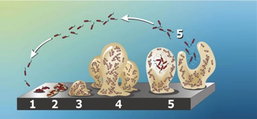
Formation sequence of bacterial growth into a biofilm (Internet)
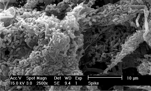
Electron microscope picture of bacteria in a biofilm (Internet)
Macrofouling
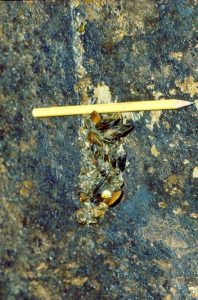
Macrofouling is usually thought of as colonising the intake system of direct-cooled power stations. The problems caused by the blue mussel Mytilus edulis, Sabellaria species, oysters and barnacles are central examples. In non-tidal low salinity waters such as the Noordzee canal in the Netherlands, the brackish water mussel Mytilopsis leucophaeata is found, while in freshwater the equivalent is the zebra mussel Dreissena polymorpha and D. bugensis. In North America severe problems have been caused by D. polymorpha and the Asiatic clam Corbicula species, which is now also found in several European river systems. The photograph below illustrates the marine biofouling process in seawater, which begins with the attachment of barnacles, followed by the settlement and growth of mussels. They settle in a formwork joint of the inlet concrete conduit at water velocities exceeding 2 m/s. This small construction extrusion causes a minor turbulence enabling mussel and barnacle spat to get holdfast on the concrete. A couple of weeks later the fouling plaque looks like this picture. The pencil shows the flow direction.(Photo: KEMA).
However, fouling is not restricted to micro- and macro-fouling, as three other types of problems could be considered in this category. Firstly, there is the material generally known as trash. In front of the intake pits, before rotating screens trash racks are situated. The trash consists of inert debris, seaweed, hydroids reeds, plastic bags and bits of wood. The rotating screens directly in front of the cooling water pumps generally remove most of the smaller trash like free-floating material and living material such as Sea Gooseberries (Pleurobrachia pileus), jellyfish and fish. The latter include those species which form shoals as they migrate in the near shore waters from which the cooling water is withdrawn, such as Sprat and smelt. Also important are those species drawn into intakes on their migratory movements into and out of estuaries and rivers like the Shad (Alosa spp.), salmonids and eels.
Historically, dosing of Na-hypochlorite (chlorination) at the front of the intake water system is still world wide the method of choice to mitigate and control biofouling. A new method to combat mussel and oysters fouling is Pulse-Chlorination® which uses the behavioural response of the bivalve in a on/off dosing regime. This method proofed to be highly effective in combination with less chlorine use as possible. The search initiated by KEMA for a more sophisticated dosing regime was initiated by the identification and governmental criticism on the formation of chlorination by-products (CBPs). Several of those CBPs are indeed identified in power plant effluents during chlorination, and early toxicity tests suggested that these CBPs might be toxic at low parts per billion concentrations. Although it has not been possible to confirm the toxicity results, these potential environmental and public health implications sparked the first interest in a search for reducing the yearly dosed chlorine load and the search for alternatives to chlorine.
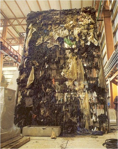
Trash rack, lifted out of the intake by EDF, showing severe fouling with plastics (Foto EDF)
Secondly, inland stations using cooling towers may face scale formation: the deposition of chemicals as a layer on the cooling-water side of heat exchangers. This resembles processes related to biofilm formation on the same surfaces. Make-up water quality, circulation flow rates and condenser inlet and outlet temperatures strongly influence scale formation.
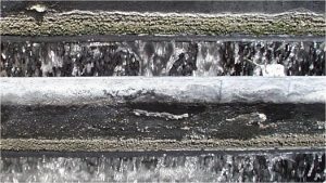
Scaling and biofouling (algae and biofilm) at a cooling tower (Internet)
Thirdly, silt may be deposited from make-up water with a high suspended-solids load. This causes trouble in low-flow zones, especially cooling tower ponds, and may enhance biofilm growth by becoming entrapped in the xPS layer. As a result, deposits in condenser tubes and on cooling tower packing can become thicker than bacterial biofilms alone.
Further information can be provided on request through the contact form.